

Engineering Workflow
From requirementsto a reviewed design.
One engineering workflow for Cleanroom, Healthcare and Commercial: project basis, room requirements, calculated and adopted airflow, results review and documentation.
Start the workflowProject & design basis
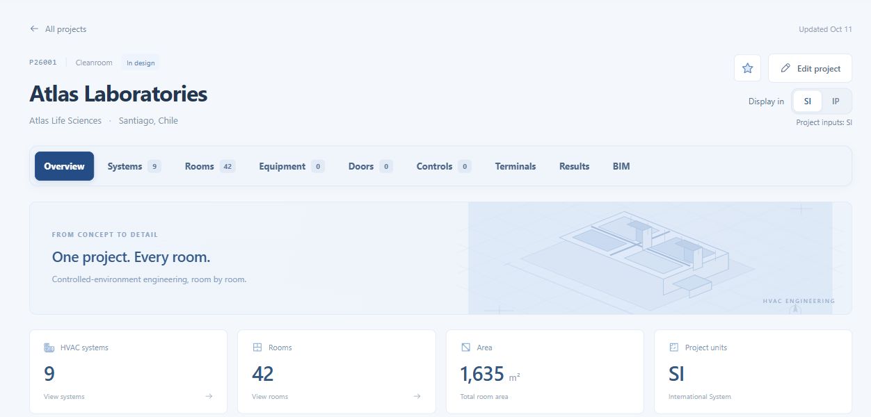
Establish the context for every decision.
Identify the project, customer, location and units. Choose the initial design profile and record the common design basis before detailing systems and rooms.
 Enlarge screenshot
What you work with
- Project identity and design units
- Exterior design conditions and altitude
- Initial profile: Cleanroom, Healthcare or Commercial
In the applicationProjects → Project → Summary
Check the design basis and initial profile. Existing rooms retain their assigned profiles.
Systems & operating conditions
Give the design its system boundaries.
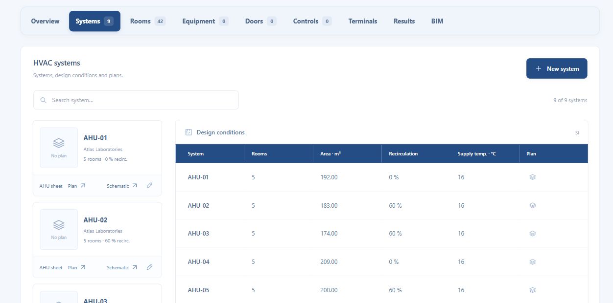
Organise the AHUs and ventilation systems, describe their operation and link each room to the system that serves it.
 Enlarge screenshot
What you work with
- System code and technical description
- Supply temperature and recirculation criteria
- System layout and room assignment
In the applicationProject → Systems
Check room assignments and the operating conditions used for each system.
Spaces, requirements & loads
Define the conditions room by room.
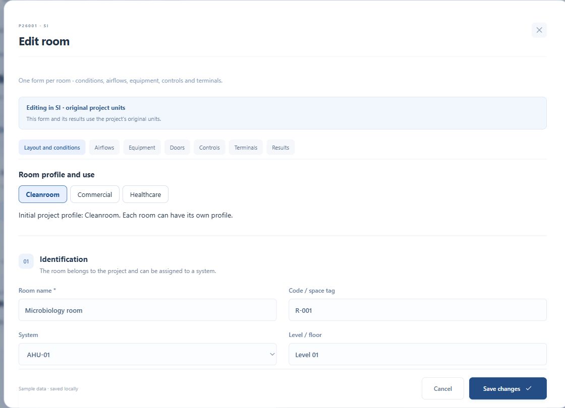
Define the profile and use of each room alongside its geometry, environmental conditions and internal loads. Rooms with different profiles can share the same project.
 Enlarge screenshot
What you work with
- Room profile and applicable use
- Code, geometry, temperature and humidity
- Occupancy, lighting, envelope and equipment loads
- Classification, pressure and air-change criteria where applicable
In the applicationRoom → Layout & conditions
Review the selected use and its conditions of application. The project profile provides a starting point; the room profile determines its requirements.
Doors, pressures & transfers
Connect the rooms through their air balance.
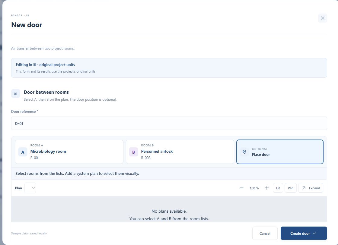
Define the rooms on either side of each door or transfer. Review how their pressure relationship and opening data contribute to the airflow balance.
 Enlarge screenshot
What you work with
- Connected room codes
- Door geometry and leakage criteria
- Pressure relationship and transfer direction
- Automatic plan: transfer arrows, airflow, room pressures and ΔP
In the applicationProject → Transfers / Room → Doors
Room pressure uses the atmosphere as reference. The difference between connected rooms determines the pressure relationship.
Calculated & adopted airflow
Make the adopted airflow a clear engineering decision.
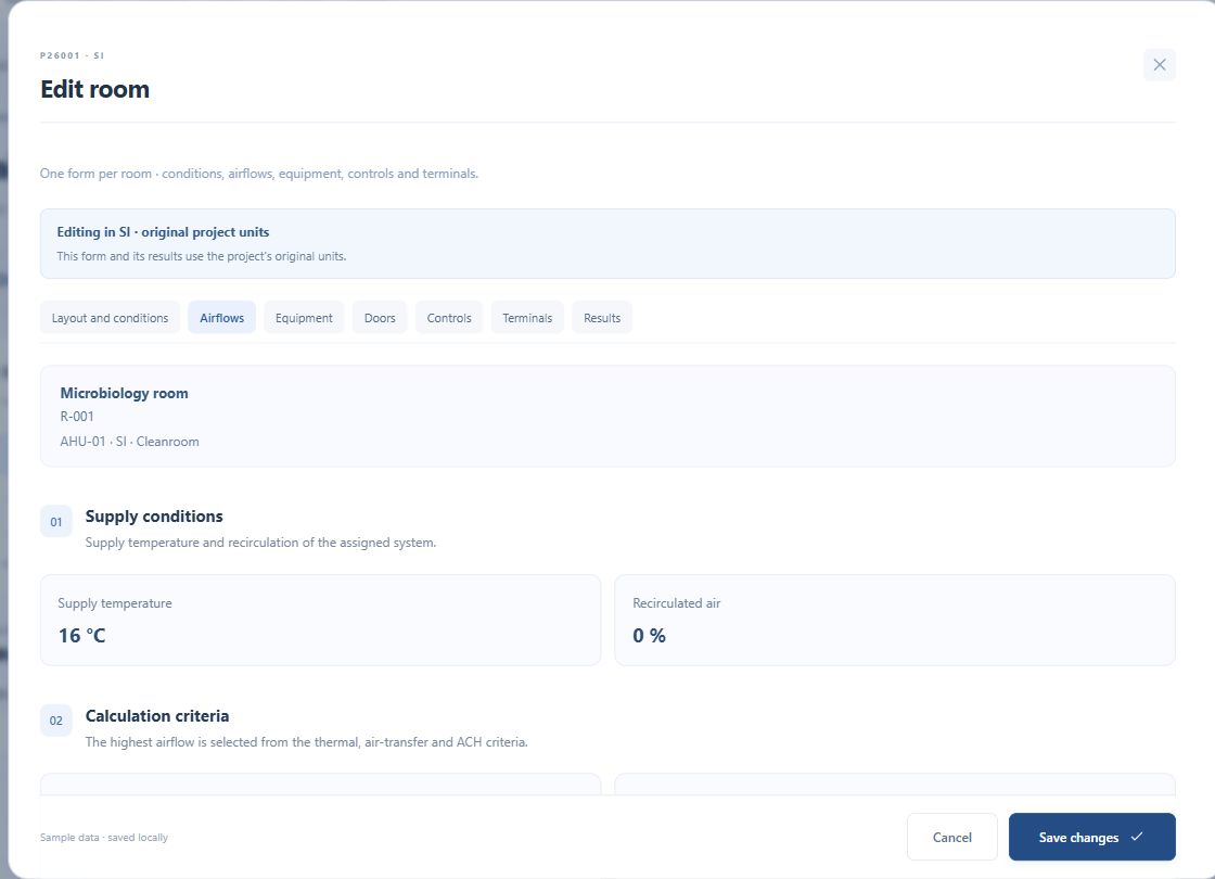
Review thermal load, air changes and transfer requirements together. Commercial and Healthcare add the ventilation requirements of the selected use to the calculation. Compare the calculated airflow with the supply, return and exhaust values adopted by the engineer.
 Enlarge screenshot
What you work with
- Thermal, air-change and transfer criteria
- Profile-specific ventilation requirements
- Outdoor air and system recirculation
- Calculated versus adopted room airflow
In the applicationRoom → Airflow
Check the governing criterion and the completeness of the calculation. The engineer adopts the airflow and reviews the conditions behind it.
Terminals & control devices
Translate airflow into the room arrangement.
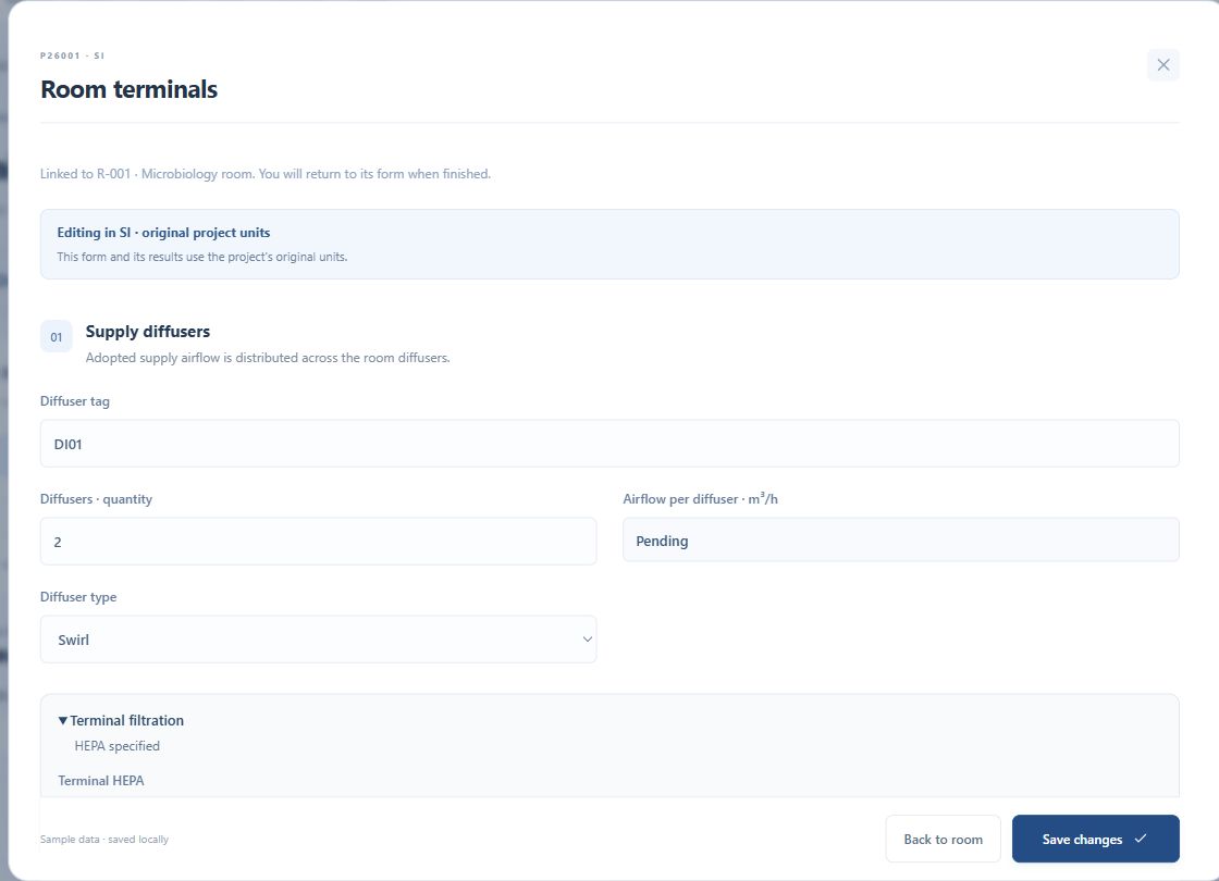
Assign supply, return and exhaust terminals to their rooms. Keep the selected quantities, tags and airflow rates connected to the adopted air balance.
 Enlarge screenshot
What you work with
- Diffusers, grilles and terminal HEPA criteria
- Terminal quantities, tags and airflow
- Airside devices and control / regulation information
In the applicationProject → Terminals / Airside
Compare terminal totals with the adopted room flows.
Results & design review
Review the design against each room profile.
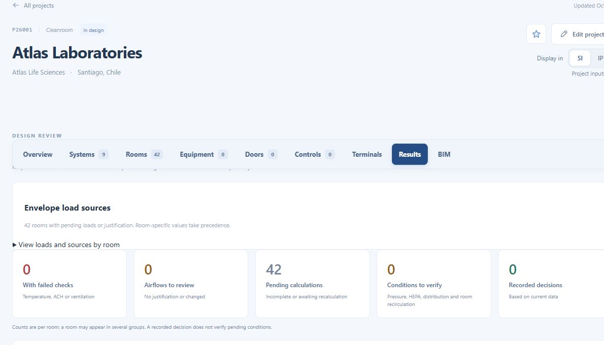
Compare required values, design results and review status by room. Commercial and Healthcare include checks of outdoor air and, where applicable, total supply or exhaust airflow. Keep design conditions awaiting verification visible.
 Enlarge screenshot
What you work with
- Temperature and additional air-change criteria
- Outdoor air and applicable total airflow requirements
- Adopted airflow against calculated airflow
- Adopted criterion, justification and pending checks
In the applicationProject → Results → Review room
Pressure relationships, filtration and conditions of application require engineering verification. An airflow decision keeps the remaining checks visible.
Documentation & BIM coordination
Carry the engineering into the deliverables.
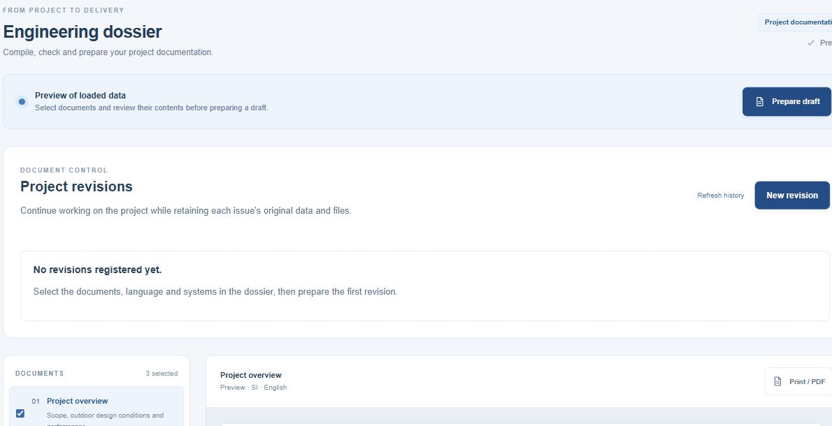
Bring together AI-generated FDS narrative chapters, room reports and results tables. The narrative uses project data and deterministic calculations as its technical basis. Review language, units and content before issuing the documents.
 Enlarge screenshot
What you work with
- Functional Design Specification · FDS
- Technical results tables · TR
- Automatic system schematics and air transfer / ΔP plans · PDF
- Room and terminal parameters for Revit coordination · Enterprise
In the applicationProject → Dossier / BIM

Generate the FDS narrative from project data. Review room reports, pending checks and narrative currency before preparing and issuing the delivery.
A continuous engineering workflow
Review. Refine. Document.
Each stage shares the project data. Return to the relevant inputs when a result needs attention, review the effect and carry the adopted design into the documentation.